Exploration on pre-crimping process of steel drum bottom
Xin Qiaojuan
In recent years, five-layer rectangular crimped steel drums have been unable to meet market demand. Export products require high strength and good sealing of steel drums. Seven-layer round curling barrels came into being in China.
According to the experience of most manufacturers, the pre-rolling of the top of the seven-layer round-edged bucket is an important process. The pre-rolled bottom of the bucket is easily formed with a seven-layer crimp when assembled with the barrel. Therefore, this production process is accepted by most manufacturers. However, this process is still not very mature, and most enterprises still have different degrees of problems in production and technology. For this reason, the author has carried out a serious systematic exploration to improve and improve the steel barrel process for the development of industry technology. make a contribution.
Figure 1 shows the pattern and dimensions of the bottom of the 200-liter closed steel drum. At the same time as the pre-rolling, fill the small circular arc into the sealant and place it for 24 hours to form a large flat annular seal. The seal is encased in the center of the seven-layer round curl when the package is packaged, providing excellent sealing.
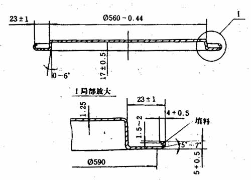
Figure 1 200 liter closed steel drum bottom top prerolled figure
Figure 2 is an outline view of the top of the barrel top pre-roller. The machine can spray glue while pre-rolling. The working principle of the pre-roller is as follows: the motor is driven by the deceleration wheel to drive the lower plate; firstly, the bottom of the bucket (top) is placed between the upper and lower plates from the side; the upper plate is driven by the cylinder, and the bottom of the bucket is tight. Tightly clamped between the upper and lower discs and rotate with the lower disc; then, the right pre-rolling roller is driven by the cam to move to the left through the slide rails, leaning against the bottom (top) edge of the bucket, so that the bottom (top) edge of the bucket is along The roll roller is rolled up in the arc; at the same time, the spray gun sprays the sealant on the edge of the barrel. Under the action of centrifugal force, the glue moves into the rolled circular arc to form a complete and uniform rubber ring; then, the cam turns into the trough and the roller exits; then the upper cylinder moves to move the upper plate up and away from the bottom of the barrel ( Top); the bottom of the barrel (top) loses its clamping force and is driven by the inertia of rotation to pull out the pre-roller. Then repeat the above process. Figure 3 is a simplified diagram of the pre-roll process. The rotation of the cam that drives the roller is obtained by the motor via the reducer. A travel switch is installed beside the cam for automatic control of the cylinder and glue. Figure 4 is a schematic diagram of the automatic control of the pre-roller.
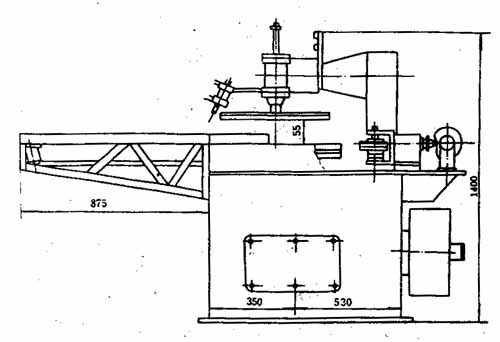
Figure 2 Outline drawing of the top of the barrel top pre-roller
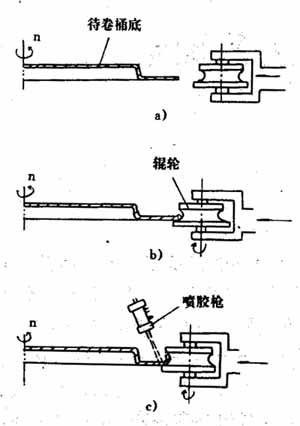
Figure 3 barrel top prerolling process
The compressed air is filtered through a filter regulator Y4 and sent to the system. The gas path 1 is adjusted to a given pressure by the pressure regulating Y1 and enters the upper disk action cylinder through the electromagnetic valve F1; the gas path 2 is regulated by the pressure regulating valve Y2 and then enters the spray gun through the electromagnetic valve F2 to control the spraying and stopping action of the spray gun; 3 After the pressure regulating valve Y3 is regulated, it enters the rubber cylinder, so that the glue is sprayed out by the spray gun with a certain pressure. The solenoid valve F1 is controlled by the stroke switch K1; the solenoid valve: F2 is controlled by the stroke switch K2; both K1 and K2 are mounted on the camshaft, and are controlled by the feed action of the roller. Adjusting Y1 makes the pressing force of the cylinder sufficient; adjusting Y3 makes the spraying speed sufficient and does not cause serious splashing. The structure of the spray gun is shown in Figure 5. The pressure glue enters the rubber chamber from the C port; when the compressed air enters from the A port, the valve core is pushed to move to the right, the top end blocks the glue port D, and the glue liquid is sprayed out; when the solenoid valve F2 (Fig. 4) In the reversing direction, the compressed air enters from the B port, and the spool moves to the left, the D port opens, and the pressure glue is ejected from the nozzle.
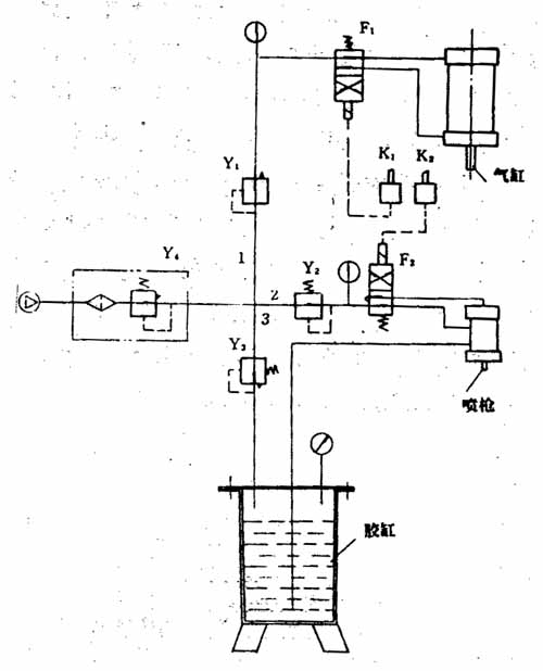
Figure 4 Automatic control diagram of the pre-roller spray cylinder
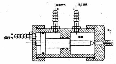
Figure 5 spray gun structure
In actual production, it is the glue dispensing system that is of particular concern. Because the sealant is easier to dry, when adding glue to the glue tank, the excess glue in the cylinder should be poured out, and the glue tank should be washed with water. Then put the water on, start the action, rinse the whole spray system with water, then pour out the water, filter the new glue and the residual glue with 50 mesh copper mesh and add it to the glue tank for use. In order to prevent the latex from drying out, the rubber road is blocked.
The latex to be used should be inspected for compliance with the production process requirements. It is generally required that the appearance of the latex be grayish white or a viscous liquid with a slight pink color, and no impurities or agglomerates may be present. When used, the pH is adjusted to 6-8, the viscosity is 3500-3700 Torr, the specific gravity is 0.95-1.0, and it can be diluted with water or distilled water.
The bottom (top) parts of the barrel after pre-rolling should have smooth and uniform peripheral arcs, no strain and curling. The latex in the arc should be even and fill the arc. After drying, a uniform annular sealing rubber ring is formed. The bottom (top) surface of the bucket should be clean and free of glue spots. The dimensions of each part shall conform to the dimensions required for the part drawing.
When the angle of the spray gun is not right or the pressure is too high, the spray gun is severely splashed. The angle of the spray gun should be adjusted or the pressure regulating valve Y3 should be adjusted to make it suitable.
If the bottom of the bucket (top) is stationary during the pre-rolling process, that is, the bottom of the bucket (top) slips on the lower disc, which is the reason for the insufficient clamping force of the upper and lower discs, the pressure regulating valve Y1 should be adjusted to make the pressure sufficient.
Pre-roller winding machine should be designed according to product requirements, in practice, be amended. The roller material can be T10 or Cr12 steel. Arc-shaped portion should be smooth and uniform. The finished roller should be heat treated to have sufficient hardness to extend its service life.
If you, a loved one or a patient is struggling to get in and out of bed, or frequently suffers from or poor`s night's sleep, then our range of hospital beds could be precisely what you need. Electric hospital beds are designed to ease discomfort and improve sleep quality, while also allowing the user to enter and exit the bed with ease. They are extremely common in hospitals and care homes, as they meet the needs for patients compared to standard beds.
The clearly marked handset is simple to use for both carers and end users alike. A Five Function Hospital Bed is a four section electrically motorised bed with electronic back rest, foot rest and knee break. It will adopt trendelenburg and reverse trendelenburg positions. It can be raised and lowered electrically, and has full length side rails that can be adjusted to ensure user safety when resting or sleeping.
Movable Hospital Bed,Patient Medical Bed,Medical Beds Electric,Hospital Electrical Bed
Jiangmen Jia Mei Medical Products Co.,Ltd. , https://www.jmmedicalequipment.com