Radio Frequency Identification (RFID) is an emerging automatic identification technology in recent years. It combines radio frequency identification technology and IC card technology to solve the problem of passive and contactless reading and writing in the card.
The application of RFID technology in the water sales system has changed the traditional meter reading charging mode, and realized the “pay-as-you-go†and card-holding modes with non-contact smart cards, improving enterprise efficiency and capital recovery rate, and reducing the labor intensity of meter reading. Promote the informationization and modernization of enterprise management.
1 RFID system works
1.1 Hardware components
(1) Tag (Tag). It consists of a coupling element and a chip, each tag having unique electronic data attached to the object to identify the target object.
(2) Reader (Reader). Devices that read electronic tag information can be designed to be handheld or fixed. It is used to transmit a radio frequency signal and receive a signal reflected back by the electronic tag, and after processing, obtain tag data information.
(3) Antenna (Antenna). Transfer device signals between the electronic tag and the reader to control data acquisition and communication. The antenna and reader are generally integrated.
1.2 Working principle
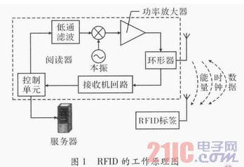
The working principle of RFID is shown in Figure 1. The reader emits electromagnetic waves in a certain area. The electronic tag has a resonant circuit that, when the tag enters the magnetic field, generates an induced current to extract energy, a clock, and an instruction, and transmits the useful data in a backscatter modulated manner. After receiving the data of this tag and decoding it, the reader sends it to the central information system for data processing. In this way, the reader can realize contactless reading through the antenna and recognize the data stored in the electronic tag, thereby achieving the purpose of automatically recognizing the object.

2 The overall design of smart card water sales system based on RFID technology
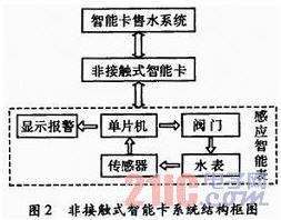
The non-contact smart card water sales system is mainly composed of three parts: a water sales system, a smart card, and a smart meter. The system structure block diagram is shown in Figure 2. The smart card corresponds to the "tag" in the RFID system, and the single-chip system constitutes a "reader". The water meter integrated with the reader function is an inductive smart water meter.

The smart card water sales system is composed of a PC, a background software, and a card sales management machine. The information transmission carrier is a contactless smart card that the user needs to purchase, and the user purchases the water amount from the water company and stores it in the smart card. When the user needs water, use the smart card to swipe the card in the smart meter sensing area. After the smart meter system reads in the amount of water, open the valve to supply water. In the process of water use, the user's water balance is decremented by a certain amount through the pulse acquisition module. When the purchased water is used up, the single-chip sends a signal to drive the valve to close.
3 hardware system design
3.1 Smart Watch
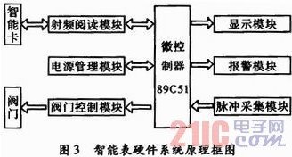
The smart meter is a water meter integrated with the reader function in the RFID system, and is mainly composed of a radio frequency card reading module, a microprocessor 89C51, a valve control module, a pulse acquisition module, a display alarm, and the like. The block diagram is shown in FIG. 3, and the above module is The logic design cooperates to complete the reading and writing of the RF smart card through the software program control, and at the same time control the switch of the valve.

A permanent magnet and a reed switch are installed in the water meter counting turntable, wherein the permanent magnet is mounted on the counter disk, the double reed switch is fixed near the top of the counter disk, the counting disk is rotated once, and the permanent magnet passes through the double reed switch once, Two metering pulses are generated at the signal end. When receiving a valid metering pulse, the single-chip microcomputer changes from the sleep mode to the working mode, and the microprocessor executes the corresponding metering program, and the smart meter calculates the remaining amount in the table in real time; when the user water balance is small, the water meter automatically alarms. Remind the user to recharge the water as soon as possible; when the user balance is zero, drive the valve control program, the valve is closed, and the data is saved in the internal Flash.
3.2 Contactless smart card
As the information transmission medium of the system, the smart card determines the data transmission form of the system and uses the wireless radio frequency to exchange data. The smart card of the system is a kind of radio frequency card. The smart card integrates components such as chips, induction coils and capacitors and is packaged in a standard PVC card. When reading and writing, the RF card is placed close to the reader, and the electromagnetic wave emitted by the reader antenna generates an induced current on the antenna inside the card to provide energy for the integrated chip in the card. The integrated circuit chip in the card stores a unique digital identification number input during manufacture. After the number is encoded, the current signal on the antenna is modulated and transmitted back to the reader in the form of electromagnetic waves. The reader transmits the received wireless signal to the field controller, which performs signal processing by the field controller and issues an instruction to the executing device. Most smart cards encode the identification number (ID number) in the card into a Manchester code and are decoded by the microcontroller.
3.3 RF antenna
The RF antenna design is an important part of non-contact reading and writing. The system uses the wireless RF sensing component GB9. The main technical indicators of communication are: transmission frequency 125 kHz; power supply DC+5 V/90 mA; read distance >100 mm. The data required to read or write the card is received and transmitted by the data receiving end (RXD) and the transmitting end (TX) of the serial port of the 89C51. When reading smart card data, its P. The level generated by the LED terminal can interrupt the INTI of the 89C51, thereby starting the interrupt handler to process the data accordingly.
4 software design
The software system design adopts the modular design mode. The main control program includes system initialization, interrupt type judgment, display processing, and power consumption mode processing. The system initialization includes setting the port, interrupt, and LCD control register. After the system is initialized, it enters the power-saving mode until an interrupt source wakes up and enters the corresponding interrupt service routine. The function module subroutine includes: a swipe subroutine, a water meter fault subroutine, a valve control subroutine, and a water flow collection subroutine.
4.1 System main program design
The main functions of the contactless smart meter implementation are:
(1) The user takes a smart card to the water department to pre-purchase a certain amount of water, then swipes the smart card close to the smart meter sensing area, the smart meter reads the water quantity information, controls the valve to open, and the water meter enters the working state.
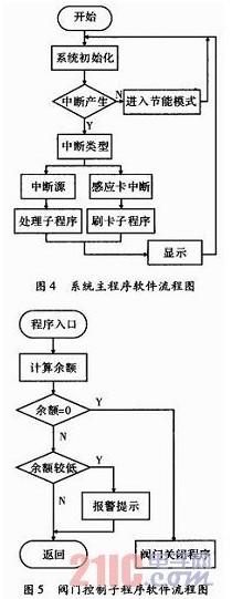
(2) In the process of water use, the water meter will save the “total water consumption†and “water balance†to the Flash RAM area in time. When the water balance is zero, the valve control subroutine is started. The main program software flow, as shown in Figure 4.

4.2 Valve Control Function Subprogram
The valve control subroutine controls the solenoid valve switch by reading the remaining water amount according to the amount of the balance. At the same time, if the balance is relatively low, the system system issues an alarm signal to remind the user to recharge. The valve control subroutine software flow is shown in Figure 5.
5 key technology design
5.1 System Power Consumption Issues
Conventional water meters do not require a power source, and even if there is a power source, they are subjectively cut off, causing the system to fail. Therefore, the smart meter is powered by an alkaline dry battery, but the capacity of the battery is limited, and the study of the power consumption of the water meter is particularly important. The energy consumption of the smart meter is mainly composed of three items: the first item is the energy consumption of the single chip operation and the LCD display. The second item is the instantaneous energy consumption when the smart meter execution unit is running. The third item is the power consumption of some auxiliary functions such as audible alarms. The first item is the most important, so the first step is to analyze the power consumption of the single-chip microcomputer, and divide the effective power consumption and the invalid power consumption in the application operation into time and space domain respectively, and concentrate the time and space domain of the effective power consumption. The application software optimization program achieves a comprehensive reduction in consumption.
5.2 Automatic error correction of data
In order to prevent the phenomenon of water theft, most of China's water meters are installed outdoors, and in the environment of interference for many years, data interference may occur when the external strong electricity, strong magnetic and other interferences occur. Although it occurs less frequently, the number of user tables is large and the coverage is wide, which should be taken seriously. For this kind of imagination, the data automatic error correction technology is adopted: the capacity of the memory is increased, the data is synchronously stored in five different positions, and when reading data, the data is read from 5 at the same time, and the reading is analyzed. As long as three or more of them are the same, the data is considered valid, and at the same time, the error-corrected data is subjected to error correction processing. This will reduce the disputes caused by non-subjective confusion of smart watches.
5.3 Anti-vibration design
The vibration of the smart meter caused by the flow of water will cause multiple counting and sampling of the magnetosensitive element, resulting in inconsistent electronic counting and wheel counting. For this problem, the hysteresis comparator can be used to make the magnetosensitive element into a special hysteresis. When the magnetosensitive element is attracted, the magnet needs to be close to the magnetosensitive element by 5 mm, but to disconnect the magnetosensitive element, the magnet needs to be moved away from the magnetosensitive element to 8 mm, so that the vibration can be effectively solved. Counting problems.
6 Conclusion
In the application process, in the case of strong electromagnetic waves and other complex interference, the system will produce unexpected operational errors, thus enhancing the anti-interference ability of the system, which needs further research.
Acoustic Wall Panel ,Soundproof Wall Panels,Sound Panels For Walls ,Acoustic Insulation Panels
Feat Top International(China) CO.,LTD , https://www.feattop.com